- 您现在的位置:买卖IC网 > Sheet目录100 > NHD-0440WH-ATMI-JT# (Newhaven Display Intl)LCD MOD CHAR 4X40 WH TRANSM
[4]?�
� ?�
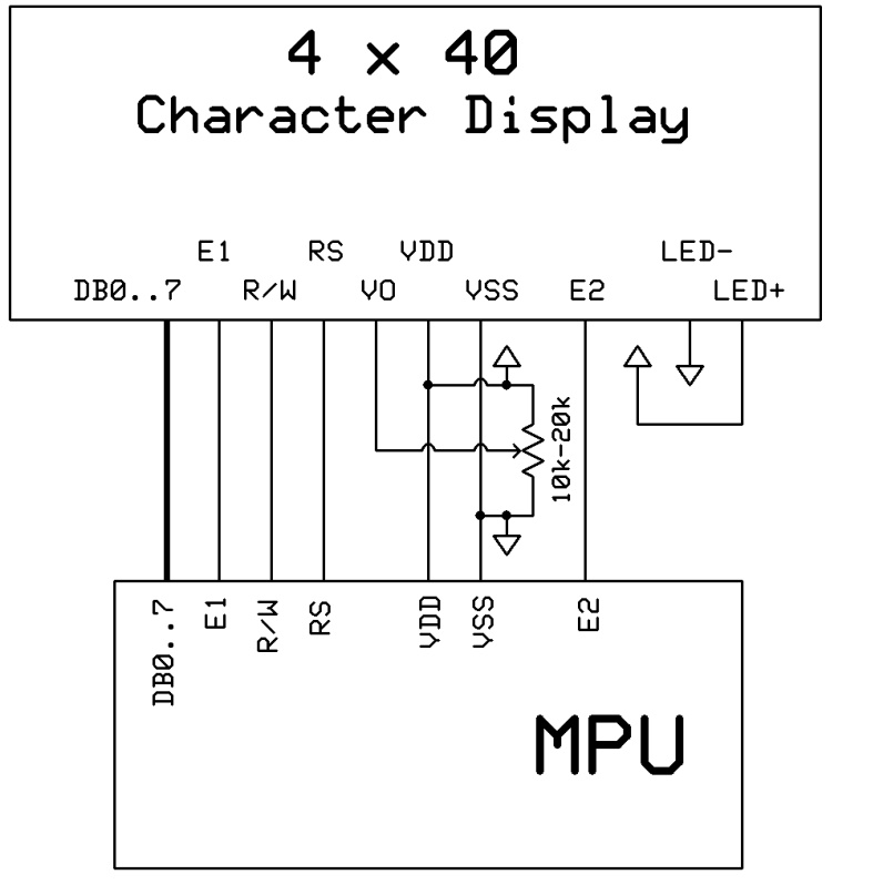
� Pin?Description?and?Wiring?Diagram?�
� Pin?No.?�
� Symbol?�
� External?�
� Connection?�
� Function?Description�
� 1‐4?�
� DB7‐DB4?�
� MPU?�
� Four?high?order?bi‐directional?three‐state?data?bus?lines.?�
� 5‐8?�
� DB3‐DB0?�
� MPU?�
� Four?low?order?bi‐directional?three‐state?data?bus?lines.?These?four?�
� are?not?used?during?4‐bit?operation.?�
� 9?�
� E1?�
� MPU?�
� Operation?enable?signal.?Falling?edge?triggered?for?top?2?lines.?�
� 10?�
� R/W?�
� MPU?�
� Read/Write?select?signal,?R/W=1:?Read?R/W:=0:?Write?�
� 11?�
� RS?�
� MPU?�
� Register?select?signal.?RS=0:?Command,?RS=1:?Data?�
� 12?�
� V0?�
� Power?Supply?�
� Power?supply?for?contrast?(approx.�
� 0.5V)�
� 13?�
� Vss?�
� Power?Supply?�
� Ground�
� 14?�
� VDD?�
� Power?Supply?�
� Supply?voltage?for?logic?(+5.0V)�
� 15?�
� E2?�
� MPU?�
� Operation?enable?signal.?Falling?edge?triggered?for?bottom?2?lines.�
� 16?�
� NC?‐No?Connect�
� 17?�
� LED+?�
� Power?Supply?�
� Power?supply?for?LED?backlight?(+3.5V)�
� 18?�
� LED‐?�
� Power?Supply?�
� Ground?for?backlight�
� ?�
� Recommended?LCD?connector:?2.54mm?pitch?pins?�
� Backlight?connector:??‐‐‐??????????Mates?with:???‐‐‐?�
� ?�
� ?�
� ?�
� ?�
� ?�
�  �
�
� � �  �
�
� � 发布紧急采购,3分钟左右您将得到回复。
相关PDF资料
NHD-1.8-128160TF-CTXI#
TFT DISPLAY MODULE
NHD-1.8-128160YF-CTXI#
LCD DISPLAY TFT 1.8" 128X160 WHT
NHD-1.8-128160ZF-CTXL#
LCD DISP TFT 1.8" 128X160 B/L
NHD-10032AZ-FSPG-YBW
LCD MOD GRAPH 100X32 GRN TRANSFL
NHD-10032AZ-FSY-GBW
LCD MOD GRAPH 100X32 Y/G TRANSFL
NHD-12032BZ-FSW-GBW
LCD MOD GRAPH 120X32 WHT TRANSFL
NHD-12032BZ-FSY-YBW
LCD MOD GRAPH 120X32 Y/G TRANSFL
NHD-12232AZ-FL-YBW
LCD MOD GRAPH 122X32 Y/G TRANSFL
相关代理商/技术参数
NHD-0440WH-ATMI-JT#100
功能描述:LCD字符显示模块与配件 4x40 STN Blue Transm 190x54mm 5V RoHS:否 制造商:Lumex 显示模式:Transflective 字符计数 x 行:16 x 2 特点: 流体类型:STN 接口: 背景色: 工作温度范围:- 20 C to + 70 C 封装:Bulk
NHD-1.8-128160EF-CTXI#
制造商:Newhaven Display International 功能描述:DISPLAY LCD TFT 24PIN 制造商:NEWHAVEN DISPLA 功能描述:DISPLAY,TFT LCD MOD,128X160, PIXEL,2.8VDD,3.2V WHT BKLT
NHD-1.8-128160EF-CTXI#-F
制造商:Newhaven Display International 功能描述:DISPLAY LCD TFT 24ZIF
NHD-1.8-128160EF-CTXI#-FT
制造商:Newhaven Display International 功能描述:DISPLAY LCD TFT TOUCH 24ZIF
NHD-1.8-128160EF-CTXI#-T
制造商:Newhaven Display International 功能描述:DISPLAY LCD TFT TOUCH 24PIN
NHD-1.8-128160TF-CTXI#
功能描述:TFT 显示器 & 附件 1.8" 128 x 160 DPI 34.0 x 47.0 x 2.7 mm RoHS:否 制造商:Sharp Microelectronics 产品:Displays 对角线:1.35 in 分辨率:96 x 96 模块大小 - 宽x高x厚:28.2 mm x 32.34 mm x 1.4 mm 观察区域 - 宽x高:24.192 mm x 24.192 mm 附加的触摸屏:No 接口:Serial 背光: 背景色: 电源电压:3 V 工作电流: 工作温度范围:- 10 C to + 60 C 封装:
NHD-1.8-128160YF-CTXI#
功能描述:TFT 显示器 & 附件 1.8 160 X 128 34.0 X 45.8 X 2.8 RoHS:否 制造商:Sharp Microelectronics 产品:Displays 对角线:1.35 in 分辨率:96 x 96 模块大小 - 宽x高x厚:28.2 mm x 32.34 mm x 1.4 mm 观察区域 - 宽x高:24.192 mm x 24.192 mm 附加的触摸屏:No 接口:Serial 背光: 背景色: 电源电压:3 V 工作电流: 工作温度范围:- 10 C to + 60 C 封装:
NHD-1.8-128160ZF-CTXL
制造商:NEWHAVEN 制造商全称:NEWHAVEN 功能描述:TFT (Thin-Film Transistor) Liquid Crystal Display Module